GPS antenna principle
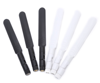
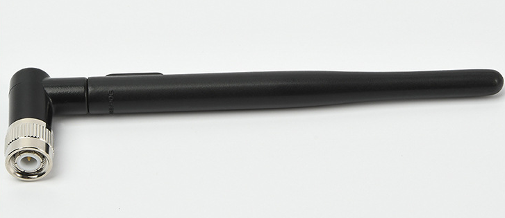
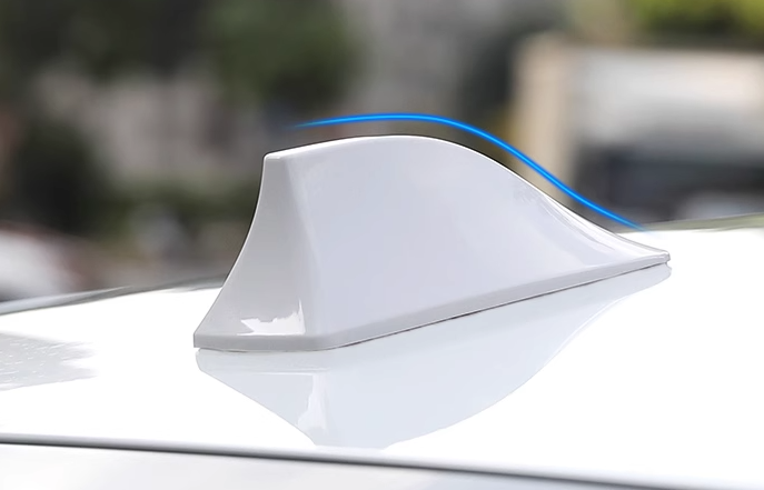
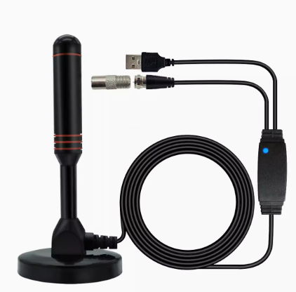
GPS is a terminal that receives satellite signals for positioning or navigation. And receiving signals requires the use of antennas. GPS antennas are divided into internal antennas and external antennas. In the early days, GPS handheld devices mostly used flip out antennas. At this time, the antenna was basically isolated from the interior of the entire machine, and EMI had almost no impact on it, resulting in good satellite reception effects. GPS antenna has four important parameters: gain, standing wave, noise figure, and axial ratio. The vast majority of GPS antennas are right-handed polarized ceramic media, consisting of ceramic antennas, low noise signal modules, cables, and connectors.
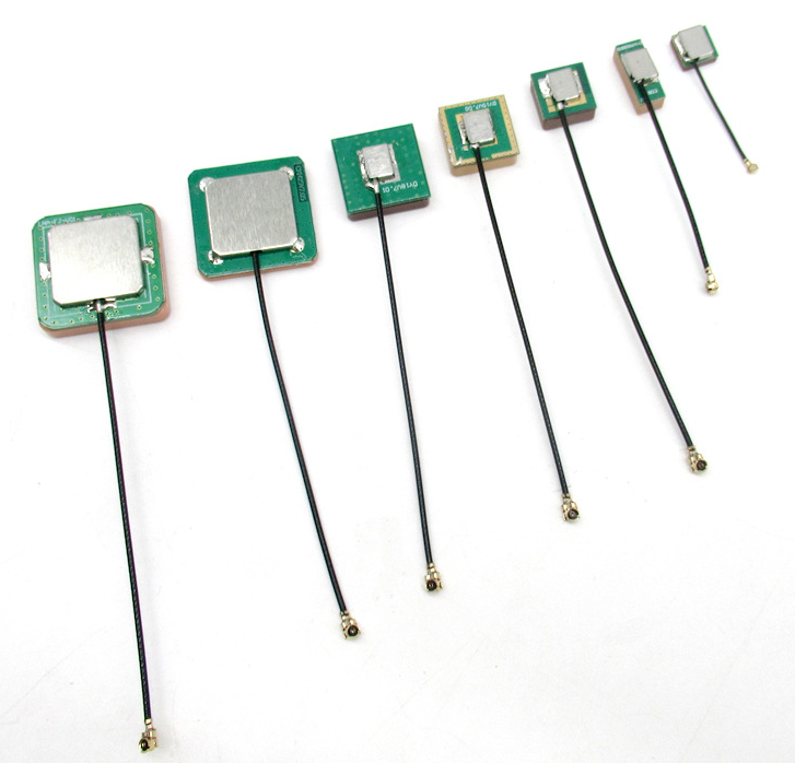
At present, the vast majority of GPS antennas are made of right-handed polarized ceramic media, consisting of ceramic antennas, low noise signal modules, cables, and connectors.
Ceramic antennas, also known as passive antennas, dielectric antennas, or PATCH, are the core technology of GPS antennas. The signal reception ability of a GPS antenna largely depends on the composition of its ceramic parts.
The low noise signal module, also known as LNA, is the part that amplifies and filters the signal. The selection of its components is also important, otherwise it will increase the reflection loss of GPS signals and cause excessive noise.
The selection of cables should also be based on reducing reflection to ensure impedance matching.
In the design of the GPS antenna unit, high-frequency and low noise amplifiers are used to reduce the thermal noise of the GPS antenna and the impact of the previous unit circuits on the receiver performance; In the principle of GPS antenna, when using GPS satellites for navigation and positioning, the main task of the user receiver is to extract pseudo random noise codes and data codes from the satellite signal, in order to further calculate the navigation information such as position, velocity, and time (PVT) of the receiver carrier. The signal carrier is in L band, and the center frequencies of the two carriers are recorded as L1 and L2 respectively. The reference clock frequency f0 of the satellite signal is 10.23MHz, and the center frequency of the signal carrier L1 is 154 times f0, which is:
fL1=154 × f0=1575.42MHz (1)
Its wavelength λ 1=475.75px; The center frequency of signal carrier L2 is 120 times that of f0, which is:
fL2=120 × f0=1227.60MHz (2)
Its wavelength λ 2=610.5px。
The frequency difference between the two carriers is 347.82MHz, approximately 28.3% of L2. This selection of carrier frequency facilitates the measurement or elimination of propagation delay errors caused by ionospheric effects when navigation signals propagate from GPS satellites to receivers. Pseudo random noise code (PRN), also known as ranging code, mainly includes two types: precision ranging code (P code) and coarse ranging code (C/A code). The bit rate of P code is 10.23MHz, and the bit rate of C/A code is 1.023MHz. Data code is the navigation and positioning data sent by GPS satellites to user receivers in binary form, also known as navigation message or D-code. It mainly includes satellite ephemeris, satellite clock correction, ionospheric delay correction, working status information, information on C/A code conversion to capture P-code, and a summary ephemeris of all satellites; The total message consists of 1500 bits and is divided into 5 subframes. Each subframe emits 10 words within 6 seconds, with 30 bits per word, totaling 300 bits. Therefore, the baud rate of the data code is 50bps.
